>Corresponding Author : Khamis A Hassan
>Article Type : Short Report Article
>Volume : 1 | Issue : 1
>Received Date : 6 May, 2021
>Accepted Date : 1 June, 2021
>Published Date : 4 June, 2021
>DOI : https://doi.org/10.54289/JDOE2100101-1
>Citation : Hassan KA, Khier SE (2021) Formation of Diagonal Gaps as Stress-Relieving Sites: Rethinking the Concept of Increment Splitting in Direct Occlusal Composite Restorations. J Dent Oral Epidemiol. 1(1). doi https://doi.org/10.54289/JDOE2100101-1
>Copyright : © 2021 Hassan KA, et al. This is an open-access article distributed under the terms of the Creative Commons Attribution License, which permits unrestricted use, distribution, and reproduction in any medium, provided the original author and source are credited.
Short Report Article | Open Access | Full Text
1Professor of Restorative Dentistry & Senior Clinical Consultant, Global Dental Centre, Vancouver, BC, Canada
2Professor of Dental Biomaterials & Senior Research Consultant, Global Dental Centre, Vancouver, BC, Canada
†Equally contributed authors
*Corresponding author: Khamis A Hassan, Professor of Restorative Dentistry & Senior Clinical Consultant, Global Dental Centre, Vancouver, BC, Canada
Abstract
The split-increment horizontal placement technique is currently used, along with other restorative techniques, in moderate-to-large occlusal cavities for reducing the shrinkage stress generated during light polymerization. Such stress, if released uncontrolled, may cause damage within the composite, tooth or at the adhesive interface. The term “diagonal cut” was used in our original paper published in 2005 to refer to the action of dividing each composite increment into segments prior to light polymerization and was presented in two-dimensional illustration. Besides, we made no mention in the original paper of the term “diagonal gap” as an outcome of such diagonal cutting. We currently recognize the importance of introducing the “diagonal gap” term and the need for shedding some light on its role to help provide a more comprehensive view of the split-increment technique. The purpose of the current paper is to rethink our increment splitting concept used in direct occlusal composite restorations by introducing the term “diagonal gap” as a stress-relieving vertical site and demonstrating it in a three-dimensional illustration for providing a more comprehensive understanding of the split-increment technique.
Conclusion: In the current paper, the term “diagonal gap” is introduced to refer to the vertical gap created by diagonal cutting of the horizontal composite increment, before light curing. This gap enables the segmented composite increment to undergo unrestrained shrinkage, where each segment being free from adhesion at the gap site can deform independently from the other segments. The relief of the polymerization shrinkage stress generated during light curing prevents formation of cracks in enamel and/or composite, and debonding of adhesive interfaces.
Keywords: Deformation, Diagonal Gap, Incremental, Occlusal, Polymerization Shrinkage, Posterior Composite, Segment, Split-Increment, Stress Reduction, Stress-Relieving Site
Introduction
Composite resins are widely used in restorative dentistry because of their superior esthetics, capability to bond to tooth structure and ease of handling. However, they possess the undesirable property of shrinkage which cannot be prevented. and ranges from 2 % to 5 %, upon light polymerization [1].
Polymerization of the composite resins is characterized by transforming monomers into polymers, and is accompanied by volumetric reduction of the material, creating undesirable shrinkage stress in bonded composite restoration [2-4].
Polymerization shrinkage stress of resin composites was directly investigated in laboratory experiments using a combination of various methodologies, and indirectly by determining the degree of microleakage associated with resin composite restorations [5].
When composite resin is placed in a cavity as one piece and bonded to the surrounding walls, shrinkage is restricted during light polymerization and generates stress. This stress is transferred to the adhesive interface as tensile forces and causes damage to the marginal seal of the bonded restoration, resulting in interfacial gap formation producing postoperative sensitivity, marginal staining, or recurrent caries. The generated stress can also cause cusp deflection resulting in patient hypersensitivity, fracture, or crack formation at the surrounding cavity walls [6].
Clinicians have traditionally restored posterior teeth in increments for the purpose of reducing shrinkage stresses while achieving proper polymerization [7,8]. The earliest among such restorative techniques is the traditional horizontal increment technique (Figure 1-A and B). In this technique, the first composite resin increment is bonded to all cavity walls [9], and during light polymerization, the constrained composite resin increment undergoes restricted shrinkage causing inward deformation of the cavity and resulting in high shrinkage stress which is transferred to the adhesive interface and the remaining tooth structure [10]. The following composite increments are individually placed to fill the cavity where they reacted upon curing in a way similar to the first increment. The effect of the resulting stress is dependent on its magnitude in comparison to the magnitude of strength of each of the composite, enamel, and adhesive interface. If the stress exceeds the cohesive strength of the composite or the tensile strength of enamel, fractures occur in the composite and/or tooth structure. If it exceeds the interfacial adhesive bond strength, it causes debonding along the interface resulting in internal or marginal gaps [11].
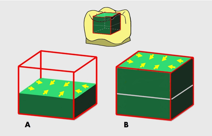
Figure 1: The “traditional” horizontal incremental technique. (A) The first composite increment (2 mm thick) is placed in a bonded occlusal cavity using this technique. Upon light polymerization of this constrained increment, high shrinkage stress develops causing inward deformation of the cavity and is transferred to the adhesive interface, tooth and/or marginal enamel causing several deleterious stress effects. (B) The second composite increment (2 mm thick) is placed to fill the cavity and reacted upon light curing similarly to the first increment.
Several other composite incremental techniques were introduced to minimize the adverse effects deriving from resin shrinkage during light polymerization, among which is the split-increment horizontal composite placement technique used in moderate-to-large occlusal cavities [12-15]. In this technique, 1-2 diagonal cuts are made in the composite increment prior to light polymerization, where the cuts result in minimizing the detrimental effects of polymerization shrinkage on the adhesive interface and cavity walls. In the original paper published in 2005 [12] and all the following ones [13-15], we used the term “diagonal cut” to refer to the action of dividing each increment into segments prior to light polymerization, with no mention of its outcome, i.e., the diagonal gap formation.
The objective of rethinking our original paper of 2005 is to introduce the term “diagonal gap” which refers to a stress-relieving vertical site intentionally created by diagonal cutting of each pre-polymerized composite increment. An additional objective is to display the diagonal gap in three dimensions for enabling better understanding and visualization of its role in relieving the generated shrinkage stresses in the split-increment composite restorations.
In the split-increment placement technique, a 2 mm thick horizontal composite increment is inserted in a bonded occlusal cavity, (Figure 2-A). Prior to light polymerization, a vertical diagonal gap is intentionally created in this increment by making a continuous 1.5 mm wide diagonal cut using a blunt plastic filling instrument in a push stroke. This gap extends for 2 mm through the full thickness of the increment, dividing it into two equal segments. (Figure 2-B) Each composite segment is free at the gap center, while bonded only to two adjacent cavity walls and half of the floor [12].
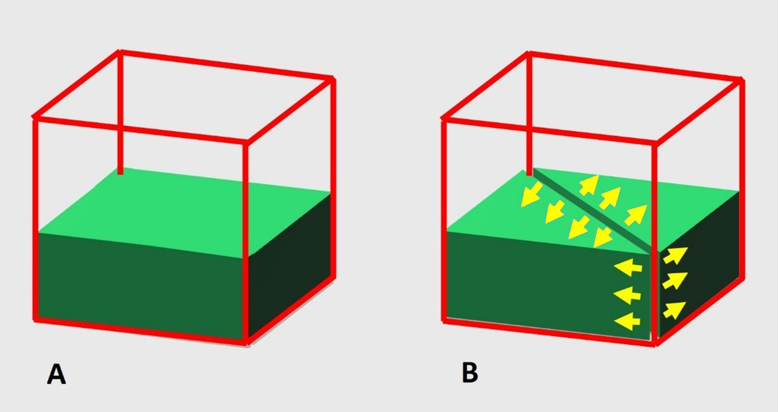
Figure 2: The split-increment horizontal technique used in a moderate-to-large occlusal cavity. (A) A first flat composite increment (2 mm thick) is placed in the cavity. (B) Prior to light polymerization, a diagonal gap is formed vertically in this increment, splitting it into two separated segments by using a blunt plastic filling instrument in a push stroke.
The formed diagonal gap creates a wide vertical break in between the two separated segments, where each can easily shrink and undergo dimensional changes during light curing independent from one another, in a direction from the gap center outwards. Thus, the diagonal gap enables the split composite increment to undergo “unrestrained” shrinkage allowing relief of shrinkage stress at the gap center without damaging the adhesive interfaces, the adjacent enamel, or the resin itself. The outward segment deformation results in a decrease in the volume of each segment, and an increase in the gap width (Figure 3-A).
Following light polymerization of the split increment, the diagonal gap is filled with composite resin making every effort not to entrap air bubbles during filling, where the composite is then light cured, (Figure 3-B) [13-15]. Considering the filling sequence of the diagonal gap and the small composite volume used for filling it, the resulting dimensional changes are not capable of generating stress in each increment sufficiently high to cause negative effects on tooth/composite resin and/or adhesive interfaces [12].
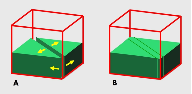
Figure 3: (A) Dimensional changes occurring in a direction from the gap center outwards, causing a decrease in the volume of each composite segment, and resulting in gap widening. (B) Filling of the diagonal gap with composite resin, and then light curing it.
The second flat composite increment (2 mm thick) is placed on top of the first one which is bonded to the surrounding cavity walls. A diagonal gap (1.5 mm wide X 2 mm deep) is created in this increment, prior to light polymerization (Figure 4-A), in the same way as previously presented (Figure 2-B), and light cured. Thereafter, this gap is filled with composite resin, where it is then light cured (Figure 4-B).
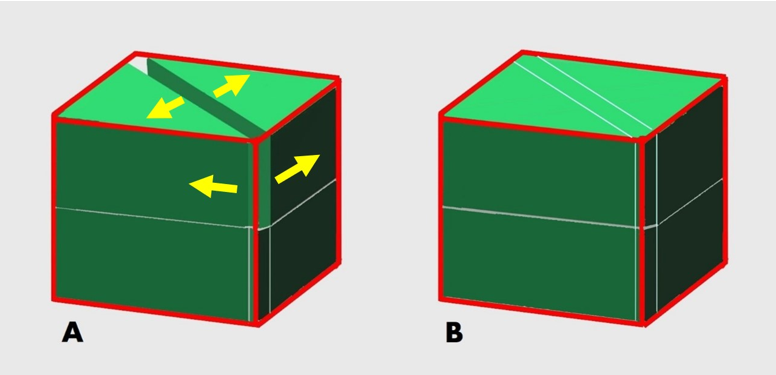
Figure 4: (A) A second flat composite increment (2 mm thick) is placed on top of the first one and is provided with a diagonal gap similar to the first gap, prior to light polymerization, and composite is then light cured. (B) Filling of the second diagonal gap with composite resin, followed by light curing.
The number of diagonal gaps created in each composite resin increment depends on the cavity width. In larger cavities, two gaps diagonally crossing each other are formed in each increment. These gaps split each increment into four segments, where each segment is free from adhesion at the gap center and is bonded only to a cavity wall and 1/4 of the floor (Figure 5-A).
This way, the two gaps do not permit a single composite increment from being connected to the four surrounding
bonded cavity walls during light polymerization which undergoes inward shrinkage and may result in damaging the adhesive interfaces, the adjacent enamel, or the resin itself.
These gaps enable each of the four segments to undergo “unrestrained” shrinkage independent of each other. The composite segment deformation which takes place at the gap site relieves the shrinkage stress and results in decreasing the volume of each segment, and widening of the two gaps, (Figure 5-B) [12,14,15].
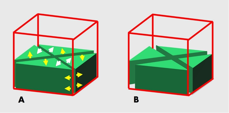
Figure 5: The split-increment placement technique used in a “large” occlusal cavity. (A) Two gaps are created along the diagonals of the increment, splitting it into four segments, prior to light curing. (B) Upon light polymerization, a decrease in the volume of each composite segment from the gap center outwards and is associated with gap widening.
Filling of the two diagonal gaps in each increment is done as follows. One gap is filled with composite resin and light cured. Then the other gap is filled with composite; one half at a time, and light cured (Figure 6).
Light polymerization of each split increment is made for 20 seconds from the occlusal direction. Finishing and polishing of the final composite restoration is done following standard procedures [12].
The number of composite increments used for restoring a prepared cavity depends on the cavity depth. The split-increment posterior composite placement technique is also used for the restoration of proximal and cervical cavities [13-16].
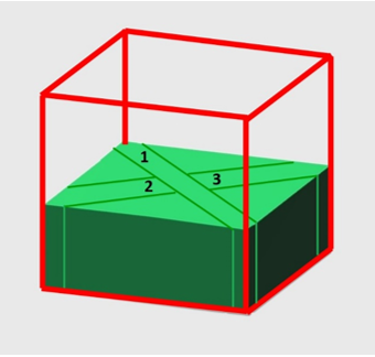
Figure 6: Filling of the two diagonal gaps in a large occlusal composite restoration, where one gap is filled completely with composite resin and light cured (1). Following that, the other gap is filled with composite; one half at a time and light cured (2, then 3).
The second flat composite increment (2 mm thick) is placed on top of the first one which is bonded to the surrounding cavity walls. Two diagonal gaps (1.5 mm wide X 2 mm deep, each) are created in this increment, prior to light polymerization, in the same way as the first ones, and light cured. (Figure 7-A) Thereafter, these gaps are filled with composite resin and light cured, the same way as with the first two gaps. (Figure 7-B)
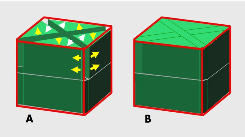
Figure 7: (A) A second flat composite increment (2 mm thick) is placed on top of the first one and is provided with two diagonal gaps prior to light polymerization, following the same steps used with the first two gaps and then light cured. (B) Filling of the second two gaps with composite resin and light curing, similarly to that of the first two gaps.
The degree of microleakage associated with resin composite restorations was determined as an indirect method for investigating the generated polymerization shrinkage stress during light curing [5]. Several research studies were carried out comparing microleakage associated with direct composite restorations placed using various incremental restorative techniques [17-20]. In such studies, the split-increment technique exhibited significantly lower degree of microleakage in the following: Class V silorane-based resin composite restorations [17], Class V extending onto the root [18], and Class II at the occlusal and gingival margins [19], as well as Class II restored with a nanocomposite resin [20].
We believe that using the three-dimensional illustrations would facilitate envisioning of the diagonal gap role in enabling the segmented composite increment to undergo unrestrained shrinkage, where the dimensional changes and generated stresses are guided to the adhesion-free diagonal gap center. In addition, we anticipate that rethinking our split increment concept in three dimensions would enable portraying the post-cure deformation of each composite segment that takes place at the diagonal gap center independently from the other segments. Furthermore, we expect that presenting our split increment concept in three-dimensional illustrations would make it possible to highlight the consequences of the polymerization shrinkage stress reduction occurring at the vertical diagonal gap, which include a decrease in the volume of each composite segment in a direction from the diagonal gap center outwards resulting in diagonal gap widening.
Conclusion
The term “diagonal gap” is introduced in the current paper to refer to the vertical gap formed by diagonal cutting of each composite increment, prior to light curing, for the purpose of relieving the polymerization shrinkage stress generated during light polymerization. This gap enables the segmented composite increment to undergo unrestrained shrinkage, where each segment free from adhesion at the gap site can deform independently from the other segments. This results in preservation of enamel and/or composite from cracking, and adhesive interfaces from debonding.
The diagonal gap is considered a key tool when using the split-increment placement technique for placing posterior composite resins in occlusal, proximal and cervical cavities.
References
- Kleverlaan CJ., Feilzer AJ. Polymerization shrinkage and contraction stress of dental resin composites. Dent Mater. 2005;21(12):1150–1157. [Ref.] [PubMed.]
- Petrovic LM., Atanackovic TM. A model for shrinkage strain in photo polymerization of dental composites. Dent Mater. 2008;24(4):556–560. [Ref.] [PubMed.]
- Cadenaro M., Biasotto M., Scuor N., Breschi L., Davidson C., et al. Assessment of polymerization contraction stress of three composite resins. Dent Mater. 2008;24(5):681–685. [Ref.] [PubMed.]
- Mantri SP., Mantri SS. Management of shrinkage stresses in direct restorative light–cured composites:a review. J Esthet Restor Dent. 2013;25(5):305–313. [Ref.] [PubMed.]
- Soares CJ., Faria–E–Silva AL., Rodrigues MP., Vilela ABF., Pfeifer CS., et al. Polymerization shrinkage stress of composite resins and resin cements – What do we need to know? Braz Oral Res. 2017;31(suppl 1):e62. [Ref.] [PubMed.]
- Baratieri LN., Ritter AV., Perdigao J., Felipe LA. Direct posterior composite resin restorations:Current concepts for the techniqtie. Pract Periodont Aesthet Dent. 1998;10(7):875–886. [Ref.] [PubMed.]
- Rosatto CM., Bicalho AA., Veríssimo C., Bragança GF., Rodrigues MP., et al. Mechanical properties., shrinkage stress., cuspal strain and fracture resistance of molars restored with bulk–fill composites and incremental filling technique. J Dent. 2015;43(12):1519–1528. [Ref.] [PubMed.]
- Versluis A., Douglas WH., Cross M., Sakaguchi RL. Does an incremental filling technique reduce polymerization shrinkage stresses? J Dent Res. 1996;75(3):871–878. [Ref.] [PubMed.]
- Braga RR., Ballester RY., Ferracane JL. Factors involved in the development of polymerization shrinkage stress in resin–composites:a systematic review. Dent Mater. 2005;21(10):962–970. [Ref.] [PubMed.]
- Chandrasekhar V., Rudrapati L., Badami V., and Tummala M. Incremental techniques in direct composite restoration. J Conserv Dent. 2017;20(6):386–391. [Ref.]
- Ferracane JL., Hilton TJ. Polymerization stress––Is it clinically meaningful? Dent Mater. 2016;32(1):1–10. [Ref.] [PubMed.]
- Hassan KA., Khier SE. Split–increment horizontal layering:A simplified placement technique for direct posterior resin restorations. Gen Dent. 2005;53(6):406–409. [Ref.] [PubMed.]
- Hassan KA., Khier SE. Composite resin restorations of large Class II cavities using split–increment horizontal placement technique. Gen Dent. 2006;54(3):172–177. [Ref.] [PubMed.]
- Hassan KA., Khier SE. A review on incremental techniques for placing direct occlusal and proximal composite restorations. Dent Oral Health Int J. 2019;1(1):1–11. [Ref.]
- Hassan KA., Khier SE. Revisiting the Concept of Diagonal Pre–cure Splitting of Horizontal Increments in Direct Composite Restorations. J Oral Health Dental Res. 2020;1(1):1–6. [Ref.]
- Hassan KA., Khier SE. Split–increment technique:An alternative approach for large cervical composite resin restorations. J Contemp Dent Pract. 2007;8(2):121–128. [Ref.] [PubMed.]
- Usha HL., Kumari A., Mehta D., Kaiwar A., Jain N. Comparing microleakage and layering methods of silorane–based resin composite in Class V cavities using confocal microscopy:An in vitro study. J Conserv Dent. 2011;14(2):164–168. [Ref.] [PubMed.]
- Khier S., Hassan K. Efficacy of composite restorative techniques in marginal sealing of extended class v cavities. ISRN Dent. 2011;2011:180197. [Ref.] [PubMed.]
- Nadig RR., Bugalia A., Usha G., Karthik J., Raghoothama R., et al. Effect of four different placement techniques on marginal microleakage in class ii restorations:an in vitro study. World J Dent. 2011;2(2):111–116. [Ref.]
- Bugalia A., Yujvender., Bramta N., Kharbanda J., Atri M., et al. Effect of placement techniques., flowable composite., liner and fibre inserts on marginal microleakage of Class II composite restorations. J Evid Based Med Healthc. 2015;2(32):4779–4787. [Ref.]